Wind Tunnel
Wind tunnel is structure used for studying the interaction between a solid or gel bodies and airstreams. A wind tunnel simulates interaction by producing a high-speed airstreams which flow passing a model being tested. The model is fixed inside testing area of the tunnel so that lift and drag forces on it can be measured by measuring the tensions on the fixing structure.
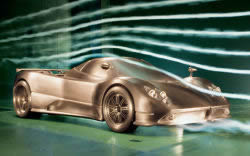
The paths of the airstream around the model can be studied with a very simple technique, consisting in placing tufts of wool (which align themselves with the wind direction) to various parts of the model. Also can be used colored oils (for surface streamlines and turbulence) and smoke (for field streamlines). For shock wave visualizations, the Schlieren photography has been used for many years. Modern wind tunnels using "Doppler effect" radars to visualize air stream, or high speed cameras with combined strobe light.
Wind tunnels may be classified according to their basic architecture (open-circuit, closed-circuit), according to their speed (subsonic, transonic, supersonic, hypersonic), according to the air pressure (atmospheric, variable- density), or their size (ordinary scaled or full-scale). There are a number of wind tunnels (meteorological tunnel called also Boundary layer tunnel, shock tunnel, plasma-jet tunnel, hot-shot tunnel) that fall in a special category of their own. In F1, pressurized wind tunnels are not allowed by FIA rules.
In wind tunnels operating well below the speed of sound, the airstream is created by large motor-driven fans. At velocities near or above the speed of sound, the airstream is created either by releasing highly compressed air from a tank at the upwind end of the tunnel testing area, or by allowing air to rush through the tunnel into a previously created vacuum tank at its downwind end. Sometimes these methods are combined, especially for the production of hypersonic velocities, i.e., velocities at least five times as great as the speed of sound.
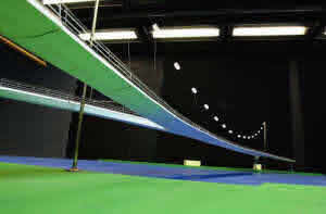 |
The effect of wind on stationary objects such as buildings and bridges can also be studied in wind tunnels (in this case called BOUNDARY LAYER WIND TUNNEL). |
Model of Ijburg Bridge in BMT's wind tunnel |
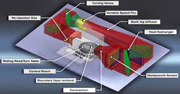
Main components of a tunnel are: Entrance cone, test section, regain passage, propeller/motor, and return passage. Flow straighteners, corner vanes, honeycomb layers for reduced turbulence, air heat exchangers and diffusers are other common features.
Pressures on the model surface are measured through small flush openings in its surface or with pitot tubes fitted on surface of tested object. Forces exerted on the model may be determined from measurement of the airflow upstream and downstream of the model.
 |
 |
 |
 |
 |
|
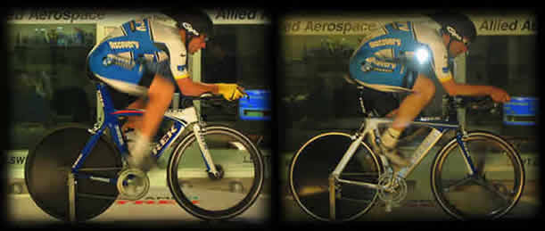
Lance Armstrong and George Hincapie in Alied Airspace Wind Tunnel |
|
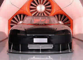
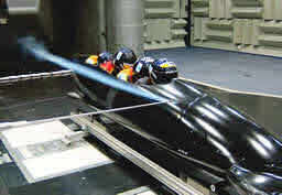
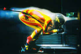
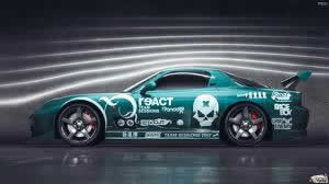
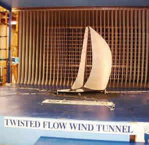 Today, wind tunnels are used in every sport where speed is important for win. Car and motorcycle racing, bicycle racing, skiing, bob sledge, wind sailing (for sail boat testing is used so called Twisted flow wind tunnel, the biggest is in Auckland, NZ) and speed boats are only some of examples where wind tunnel are used more and more to gain important milliseconds. It's easier to simulate different configurations and easier to correct mistakes in controlled environment then in the field.
Most automobiles produce lift. As the speed increases, the lift force increases and the car becomes unstable. In order to counteract this problem, modern race cars are designed to produce negative lift. The typical family sedan has a lift coefficient of about 0.3, while a F1 car can have a lift coefficient of 3.80. You can easily see the significant amount of downforce that a race car can produce. All of these things are easy observed, tested and modified in wind tunnel in controlled space with controlled air temperature and pressure, in controlled speed without actually driving the car.
A modern wind tunnel is a necessity rather than a luxury in Formula 1.
First team in Formula 1 to own their own wind tunnel was
Brabham F1 team run in this time by Bernie Ecclestone and Gordon Murray.
Such is the intensity of competition at motorsport's top level, that a 10 percent improvement in the complex and highly-sophisticated relationship between downforce and drag on the wings, body and undertay of a Formula 1 car will translate into a one-second improvement in lap time. To develop the car aerodynamics, Formula 1 teams spend an average of about $60-100 million to build their own wind tunnel at their factory.
Mercedes-Benz SLS AMG Development and Testing Wind tunnel
Aerodynamicists speak of F1 wind tunnels as a type of low-speed closed circuit tunnels. This means we are talking of airspeeds between 10 and 100 m/s approximately, and tunnels in which the same air is recirculated. Also called "racecourse" or "closed-return", which are usually powered by one fan. For some large but no so sophisticated wind tunnels several meters in diameter, array of multiple fans are used in parallel to provide sufficient airflow.
More sophisticated and expensive tunnels normally use one big fan. In this way turbulence is reduced but still highly turbulent due to the fan blade motion, and like this is not directly useful for accurate measurements. In McLaren Mercedes 145 meter tunnel, in the shape of a rectangular circuit, air is driven by a giant fan which is four meters in diameter and rotates at up to 600 rpm.
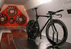
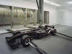
Today all F1 team have their own tunnels and some of them have two, working 24/7. From an operating room beside the tunnel, a team's aerodynamics engineers monitor a model or full scale Formula 1 car and study the computer data that define the way it reacts. Rather than moving the model - most are 50 or 60% the size of the real car, but some use full-scale models - the wind moves over the car as if the car were traveling at a given speed.
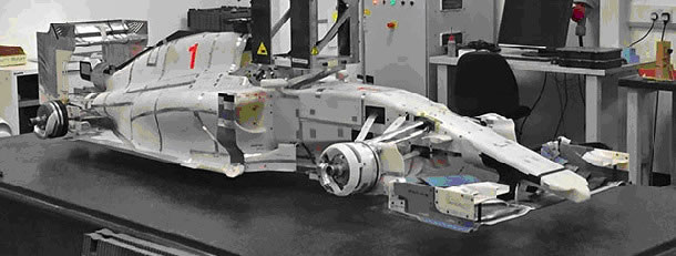 |
The "Manor MNR1" 60% scale model almost ready for wind tunnel testing in Mercedes F1 wind tunnel. The "Marussia F1" team which would have been rebranded "Manor F1" for the 2015 season was highly advanced in the design of the car before work stopped in September 2014 because of cash flow problem. |
The wind tunnel is the work place of both aerodynamics engineers and specialists in a branch of aerodynamics called CFD or computational fluid dynamics. This is a form of computer analysis that uses a computer representation of the effect of the wind on the car. It helps the engineers to see how effective the wings are and where the main areas of turbulence lie. The data is processed in a supercomputer, also owned by the team.
 Closed-circuit tunnels have more uniform flow than open circuit tunnels. These are the usual choice for large tunnels (also for Formula One), but care is needed to maintain good flow at the entrance to the contraction (called also test or observation area). The flow at exit from the fourth corner (counting from the test section upstream) is typically not much better than the exit flow from a blower, although the corner vanes themselves have some effect in reducing turbulence.
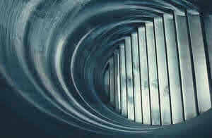
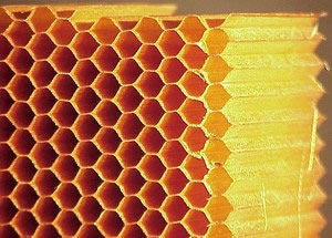 This air vanes are used to direct air trough the corners of the wind tunnel and to prevent turbulence in the corners. The air moving through the tunnel test area needs to be turbulence-free and laminar. To correct this problem, a series of closely-spaced vertical and horizontal air vanes are used in so called settling chamber to smooth out the turbulent airflow before reaching the subject of the testing. To further improve airflow, immediately before entering testing chamber, air pass trough panels with honeycomb shaped holes. Trough this holes air is further ironed and on exit is completely laminar. Finally, the ideal contraction ratio 7:1 between fan area and test area reduce turbulence scales and flow misalignments. The mode of action of a honeycomb with cells elongated in the flow direction is qualitatively obvious but few tests have actually been made, and all that is certain is that the cell length of the honeycomb should be at least six or eight times the cell diameter.
There is always a small vent, called a "breather", somewhere in the circuit so that the internal pressure does not increase as the air heats up during the run. The breather is best located in a part of circuit where inner air is close to atmospheric pressure. Usually that is around the perimeter at the downstream end of the test section.
The cooling subsystem is another crucial component of the tunnel, the heat-exchanger is located in the slowest part of the tunnel to minimize pressure losses and increase the heat transfer efficiency.
The chiller unit prevents any temperature build-up during testing within a range of 1oC to maintain the air properties constant and have the better measurement repeatability.
 |
 |
Axial fan at wind tunnel at Qinetiq |
Axial fan at NASA wind tunnel |
Most closed-circuit tunnels are driven by axial-flow fans, which produce a static pressure rise (with no appreciable change in axial velocity or dynamic pressure). The design of axial fans for tunnels is a very complex matter. It is why F1 wind tunnels usually have an especially custom designed fan to maximize the performance and decrease side effects.
F1 wind tunnel fans are usually mounted downstream of the second or third corner, where the cross-sectional area is two or more times that of the test section (ideally 7:1). It needs no explanation that a large fan can run at a lower speed to generate the same airflow, thus needing less rpm and reducing vibration, noise, turbulence and power consumption.
Special attention has been focused on the fan-straightener and the corner turning vanes to avoid any possible power losses due to swirl velocity and turbulence.
An example of such a fan can bee seen in the pictures up, which shows the fan of the NASA and Quinetic wind tunnels. Note that the engine is located in the boss of the fan, which only consists of less than half the fan's diameter.
One major advancement has been promoted by the use of moving ground planes (previously not used in other branches of aerodynamics). When in the 1970s it was discovered that downforce can be created by means of ground effect, it became essential to simulate the effect of the track on the car performance (on underbody, side pods, exposed wheels, wings). The moving belt approach is mandatory for vehicles with very low ground clearance (Formula 1 racing cars) or low drag coefficients (sports cars).
In a wind tunnel with a stationary ground plane a boundary layer build up on the "track" under the car, and can interfere with the boundary layer of the lower components of the car. Such a case cannot give the correct test results.
There are several ways to remove the ground boundary layer, but the most effective method is to use a moving belt, with the wheels rotating with the belt. The simulation of rotating wheels could not be more effective. The importance of the exposed wheels in Indy and Formula 1 has been widely recognized, and neglecting this effect may have a large effect on the overall performances.
In the most sophisticated wind tunnels the entire rolling road platform can be rotated horizontally in order to simulate not only frontal but also side-wind conditions at an angle of up to ten degrees. It is fitted with a steel belt which simulates the relative motion between the vehicle and the road. The moving steel belt reaches the same velocity as the air stream. Located underneath the moving belt are load cells, which are used to measure wheel lift during the tests. Rolling belt is sucked by a porous plate to counteract the suction of the F1 undertray. A number of vacuum area permit to control this suction and reduce the friction.
Moreover the plate where the belt slide is water cooled to increase belt lifespan and to keep "road" on the right temperature, the four wheel position are constantly monitored for temperature.
Rolling road speed is software controlled to follow wind speed and simulate the track moving under the chassis.
As I sad, the wheels are moved by the belt and rotating they reproduce the real condition of the running vehicle.
The inside facing of the tunnel is typically very smooth to reduce surface drag and turbulence that could impact the accuracy of the testing. Even smooth walls induce some drag into the airflow (boundary layer drag, remember?), and because oh that the object being tested is usually kept near the center of the tunnel, with an empty buffer zone between the object and the tunnel walls.
 With the model of the car mounted on a force balance (pole like supports usually three or five of them, two or four horizontal and one vertical), technicians can measure lift, drag, lateral forces, yaw, roll, and pitching moments over a range of angle of attack. This allows them to produce common aero curves such as lift coefficient versus angle of attack.
Note that the force balance itself creates drag and potential turbulence that will affect the model and introduce errors into the measurements. The supporting structures are therefore smooth and teardrop shaped to minimize turbulence.
A number of components internal force balance is installed inside the model, it facilitates the measurement of lift, drag and side forces, along with their moments of yaw, roll and pitch.
The model attitude can be continuously controlled during run session by software, ride height and pitch angle can be adjusted with force balances to provide a complete aero map without stop to the air flow.
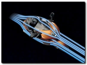
 Because is difficult to directly observe the air movement itself, a smoke or a fine mist of liquid is sprayed into the tunnel just ahead of the model being tested. The smoke is sufficiently low mass to stay suspended in the air without falling to the floor of the tunnel, and is light enough to easily move with the airflow. Also, new technology was introduced, called Particle Image Velocimetry (PIV), technology which allowed technician to visualize air flow without introducing smoke stream in very sensitive air stream in front of testing subject. Smoke probe was efficient, but the whole problem in this area is how to visualize flow without introducing something new (smoke probe) into that flow that could potentially compromise the results. The appliance of PIV posed an excellent solution to this problem.
If the air movement around tested object is sufficiently non-turbulent, a particle stream released into the airflow will not break up as the air moves along test object, but stays together as a thin line. Multiple particle streams released from a grid of many nozzles can provide a dynamic three-dimensional shape of the airflow around the object being tested. As with the force balance, these injection pipes and nozzles need to be shaped in a manner that minimizes the introduction of turbulent airflow into the airstream.
High-speed turbulence and vortices can be difficult to see directly, and strobe lights and high-speed digital cameras can help to capture events that are a blur to the naked eye. "Doppler effect" radars are also used.
Measurement equipment and testing procedures are topics on their own. They include instrumentation for the measurement of pressure, temperature, forces in 3D, moments in 3D, turbulence intensity, etc.
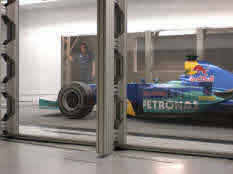 BMW Sauber F1 Team have their own Formula One's most advanced wind tunnel in Hinwill Svizerland. This facility represents the state of the art in terms of the wind speed and quality it can generate, the size of the test section and models, the dimensions of its rolling road, the model motion system and its data collection capability. This wind tunnel was build in era of Sauber Petronas team. Peter Sauber, owner of Sauber Petronas team sold the team 2005 to BMW. Peter Sauber was inventive and successful team owner.
He build most sophisticated wind tunnel (and is still today-2008), and in this time most powerful supercomputer grid in F1 and in the automotive industry as a whole.. "Albert", as the system has been named, was built using a total of 530 64-bit processors by Swiss firm DALCO. The software was supplied by Fluent. Albert is used for CFD and wind tunnel data analysis. Altogether, the BMWSauber supercomputer comprises 530 processors in a cluster architecture with dual nodes. The processors are installed in high-density cooling enclosures supplied by American Power Conversion (APC). These enclosures are self-contained, closed-loop water circuits that provide up to 15 Kw of cooling power per enclosure. The supercomputer comprises a total of ten enclosures, each one metre wide, a 1.20 metres deep and 2.30 metres high, resulting in a total width of ten metres and a weight of
18 tones.
The technical data is as impressive as the "hard facts": the supercomputer boasts peak performance of 2.3 Tflop/s and is equipped with 1 TB RAM and 11 TB of hard-drive storage
The wind tunnel has a closed-circuit design, a total length of 141 meters and a maximum tube diameter of 9.4 meters. The single-stage axial fan with carbon rotor blades, including the motor and housing, weighs in at 66 tones. A fan feeding off up to 3,000 kilowatts of power ensures wind speeds up to 300 km/h.
The core element of any wind tunnel is the test section, where the models are exposed to air flow. The extremely big cross-section and length of the rolling road create optimum conditions for achieving precise results. The tests are carried out with 60-percent models, but full-size Formula 1 cars can be used.
The engineers fit on wings and other pieces of the chassis to the model car, trying out new designs or refining existing ones. They create a constant supply of changing parts to test by using a CFD programs. Results are delivered to next computer to form a three-dimensional printing called stereolithography. A designer draws the new part on a computer, and then prints it in the machine that uses resin to construct the model part. The resin hardens into a kind of plastic, and the new part is ready to be tested in the wind tunnel within hours.
The aim is to create parts that can offer most grip (downforce) and the least amount of drag, or friction, to slow the car. Once the engineers feel that they have the best wing or chassis part they transfer the design to another department of the Formula 1 factory where the actual, real part is made out of carbon fiber at full size for the car. It is then tested on the real car by the test team at a track between races.
And so it goes on forever, as these aerodynamics and computational fluid dynamics engineers - who usually have PhDs and come from the aerospace industry - invent thousands of new parts throughout the season.
Aerodynamic resource restrictions in Formula One were introduced by FOTA in 2009 as a means to limit a team’s expenditure on aerodynamics. This limitations were optional and open to abuse. Large investments were being made in full-scale wind tunnels, enormous computational clusters and on-track testing, and cost start to get out of control. To prevent that, limits were placed on a team’s running full-size cars in a wind tunnel, track testing, wind tunnel usage time and CFD usage. Limitation are introduced for length of time the wind tunnel is switched on (with the speed above a nominal value) and harvested CFD teraflops (this is a measure of the computational usage of a CFD cluster).
For 2014, the testing restrictions are now an appendix to the sporting regulations, and are enforceable by the FIA. They are no longer optional and open to abuse. Beyond this, the two main changes for 2014 are:
- A reduction in the wind tunnel and CFD usage is limited to 30 hours and 30 teraflops
- The number of wind tunnel runs is limited to 80, and occupancy time is restricted to 60 hours (the length of time a model can be installed in the wind tunnel, having parts changed or ready to be tested)
Before, s Formula 1 wind tunnel will typically run for 24 hours a day, seven days a week, during which it can perform upwards of 200 runs, so the new restriction cuts this down to roughly a third of the old run rate. Assuming that each wind tunnel run is testing a new part, this is a dramatic reduction in the number of components that can be tested in the tunnel.
The reduction in wind tunnel testing will lead to a greater emphasis on the use of CFD in the development process. Designing parts in CFD prior to tunnel testing allows all but the most promising directions to be filtered out without wasting tunnel runs and time.
A bit of a history:
The importance of aerodynamics to automobile racing has been known throughout most of the sports history. In particular, the significance of aerodynamic drag has been known since the early days of the streamline shaped cars. However, aerodynamic effects were a secondary concern to engine, suspension, and tire technologies. The effect of aerodynamic lift or downforce on a race car was not examined in detail until the early 1960's. Today, to make the best of an aerodynamic downforce is considered to be more important than drag reduction. At 100 kph, the aerodynamic drag is dominant factor of the overall vehicle drag. For the typical sedan at this speed, the aerodynamic drag is about twice the drag due to rolling resistance. The rolling resistance increases slightly with speed while the aerodynamic drag increases with the square of the velocity. When one considers that the one-lap record speed for the Indianapolis 500 has been above 129 kph since before 1920, it is little wonder that drag reduction was a concern of the race car designer.
But history of Wind tunnel is much older than that.
Beginning in the mid-1700s, hopeful airplane designers realized that, if they want to build aircraft that would fly, they needed to understand how air moved over aircraft surfaces.
They recognized that, to get the necessary data, they had two choices: they could move their test aircraft through the air at the required velocity or they could blow air past a stationary model.
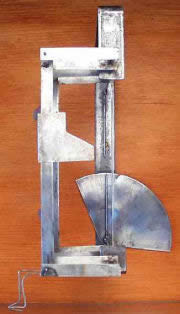
The whirling arm was early researchers' attempt at the first method. In the early 1800s, George Cayley devised the whirling arm as a way to measure the drag and lift of airfoils.
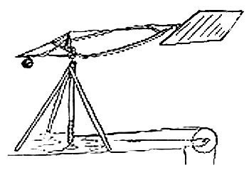 George Cayley Whirling arm
 |
The English mathematician Benjamin Robins used a whirling arm in his experiments in 1746. Robins mounted variously shaped objects on the tip of the arm and spun them in different directions. He found that the shape of the object seemed to affect the air resistance, or drag, even though equal total areas were being spun and were exposed to the airstream. He realized that the theories of Sir Isaac Newton did not adequately describe the complex relationship between drag, the shape and orientation of the object, and air velocity. |
 |
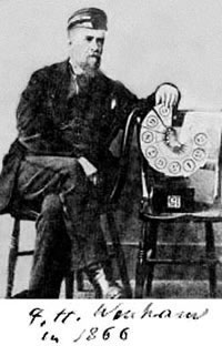
Otto Lilienthal's glider experiments were preceded by his whirling arm tests of various lifting surfaces. Between 1866 and 1889, he built several whirling arms, ranging from 2 to 7 meters in diameter. However, the tests he carried out with these arms gave incorrect results for both flat and cambered airfoils and led him to believe that powered flight was highly unlikely. |
 |
Hiram Maxim also used a huge whirling arm to test airfoils. His whirling arm included elaborate instruments to measure lift, drag, and relative air velocity. |
 |
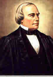
Samuel Langley, the mathematician, astronomer, and secretary of the Smithsonian Institution, was another who experimented using a whirling arm before he built his aerodromes. His whirling arm was 18 meters in diameter and its 10-horsepower engine could accelerate it to speeds of 161 kilometers per hour. But his results were thrown off by the winds and turbulence that the arm itself created. |
| The whirling arm provided a good deal of the aerodynamic data through the end of the nineteenth century. However, it had limitations. Basically, it was imprecise so the results it produced were also imprecise. For instance, the arm stirred up the air with its motion so that both the arm itself and the air it went through were moving. So experimenters took another tactic - that of blowing air past a stationary model-and began looking for a dependable way to do this. The wind tunnel was the result. This apparatus solved most of the problems associated with the whirling arm. |
|
 |
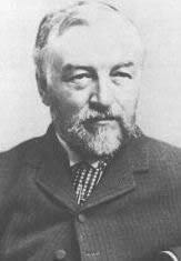
Frank H. Wenham was the first individual to design a wind tunnel. He was a self-taught British engineer whose interests spanned a wide range of engineering applications. A charter member of the Aeronautical Society of Great Britain, he lectured frequently to the Society. He persuaded the organization to raise the funds needed to build a wind tunnel, which was constructed in 1871. Wenham designed the apparatus and was the first to use it. Wenham mounted various shapes in the tunnel and measured the lift and drag forces created by the air that rushed by the shapes. Results showed that at low angles of incidence, the relationship of lift to drag of the test surfaces (the lift-to-drag ratio) was higher than expected at a low angle of attack. |
| With such high lift-to-drag ratios, wings could support substantial weights, making powered flight seem more attainable than previously thought. The research also showed that long, narrow wings, called high-aspect-ratio wings, provided much more lift than stubby wings with the same area. | |
 |
John Browning, an optician and another member of the group, built the tunnel, which was located at Penn's Marine Engineering Works at Greenwich, England. The tunnel was 3.7 meters long and 45.7 centimeters square. A steam-powered fan drove the air through a duct to the test section where the model was mounted. The air could travel at a maximum velocity of 64.4 kilometers per hour. It was an unsophisticated device. It had an unsteady airstream that made accurate measurements that could be replicated almost impossible, and had no vanes for guiding the air. Nevertheless, it yielded important results. |
| Hiram Maxim also built a wind tunnel when he realized that his whirling arm had limitations. His wind tunnel was also large, 3.7 meters long and with a test section 0.9 meter square. Twin fans blew air into the test section at 80 kilometers per hour. The tunnel and whirling arm proved to Maxim that cambered airfoils provided the most lift with the least drag. He was also the first to understand that the total drag produced by a structure was greater than the sum of the drags of the individual components - called aerodynamic interference. This concept was demonstrated in 1894 when the huge aircraft he built and "flew" developed so much lift that it tore loose from its test track and destroyed itself. | |
 |
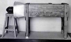
In the early 1880s, Horatio Phillips tried to carry out tests similar to Wenham's with his own wind tunnel. His tunnel was a box 1.8 meters long and 43 centimeters on each side. He directed a jet of steam through the box, blasting a series of wing shapes that he placed inside the tunnel. He hoped to find out how fast the velocity of the oncoming airstream needed to be so that each different form, which carried equal weights, would remain suspended in the airflow. |
 |
Soon after Phillips conducted his experiments, another European, this time the Frenchman Gustave Eiffel, would conduct experiments using a wind tunnel. And in the United States, the Wright brothers would design and use a wind tunnel that would prove instrumental in the success of the first flying machine. |
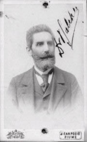 |
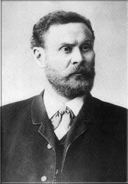
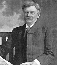
Ernst Mach began with experiments in the field of supersonic phenomena around 1875. Mach approached Petar Salcher a professor of physics at the Imperial Naval Academy of Fiume (now Rijeka, Croatia, my hometown), who had access to ballistic experiments with guns and was an experienced photographer. Salcher also studied air streams of supersonic velocity emerging from narrow nozzles together with John Whitehead. To make this, they fabricated wind tunnel as a housing for nozzels and to keep air stream stady, in old „Torpedo“ factory in Rijeka, same factory where torpedo was invented. There, the model was virtually stationary, which facilitates the application of a variety of sophisticated experimental techniques. Salcher started his experiments in 1886 and very soon successfully took pictures of flying bullets with the shock waves anticipated by Mach. |
| The pictures taken by Salcher show cones of compressed air when the projectiles velocity is higher than about 340 m/sec. These experiments became important for the development of supersonic airplanes. Irregular shock wave in jet was doubed „Lira“ by Salcher, but later came to be called „Mach disc“. In fact, the experiments were done entirely by Salcher, who coordinated with Mach only by mail. Though Mach provided guidance, recent correspondence discovered by Krehl shows that Salcher's contribution has been underrated. Discovered mails show 140 mails from Salcher to Mach, but none in opposit direction. If there is anything left to name in gas dynamics, we should name it for Peter Salcher. | |
|
|
 |
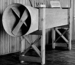 |
Replica of Wright brothers wind tunnel |
|
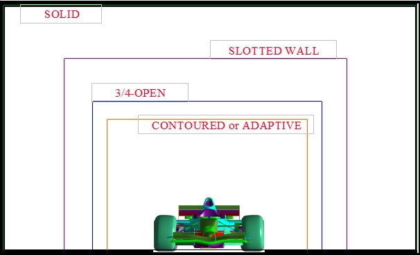
Test Section - 1: Closed, Straight Wall
Traditional configuration with approximate correction methods for main forces
Problems for testing at yaw, uncertain corrections for side forces
Causes blockage related errors so closed tunnels are built large
Generally total model/mount frontal area of 5% is considered limit but results are consistent even at higher blockages
Test Section - 2: 3/4 Open
Frequently used configuration for passenger cars especially for acoustic work
Complex aerodynamic interference with pressure gradient in working section and flow pulsations
Results may be slightly less consistent than closed jet tunnels
Blockages to 10% reasonable and to 20% can be tolerated with corrections
Low cost makes these facilities cost effective
Test Section - 3: Slotted Wall
Sometimes built into closed, straight wall tunnels to allow for the use of full-scale vehicles in a predominantly scale tunnel - designed to reduce interference
Extremely complex aerodynamic interference - no accurate correction method available
Blockages to 10% maximum
Allows the possibility of testing large models occasionally with downtime for conversion
Test Section - 4: Closed (fixed) Contoured
Has the quality of closed but no blockage corrections for one specific model so better absolute accuracy for that specific design
Productive for specific model design but requires downtime and availability of new walls if model concept changes
Future resistant if walls are readily replaceable or movable
Cost virtually as closed if shape information available
Test Section - 5: Closed, Adaptive Walled
Accepts highest blockage of all (up to 25%) with no blockage correction necessary due to adaptation of tunnel cross-sectional area at each station
Ideal configuration if tunnel big enough
Adaptation of tunnel walls reduces testing efficiency slightly with single model specification but is perfect for complete changes of vehicle type
Cost of test section adaptive equipment increases costs but allows a smaller facility with few, if any, downsides
|