Crash Test
All new F1 cars, before the start of the season, must pass crash test under the supervision of the FIA. All together there are 18 different tests to be done. Some structures are tested few times in different ways, and that is giving combination of 18 different tests.
The dynamic and static tests simulate frontal, rear and side impacts and test of the roll bar. All tests must be carried out in accordance with FIA Test Procedure, in the presence of an FIA technical delegate and by using measuring equipment which has been calibrated to the satisfaction of the FIA technical delegate.
After any significant modification on survival cell or crash structure during the season, static and dynamic test must be repeated on modified part. But, every new produced survival cell must be subjected to only static crash test. Survival cell must have passed every static load test before being subjected to any impact test.
Composites are largely unrivalled as a material for impact absorption, with a specific energy absorption (SEA, measured in kJ per kg of material used) far higher than their metallic counterparts – providing sufficient optimisation.
The decision to use CFRP for impact absorption is a fairly easy one. Comparing the SEA-s of various materials, steels achieve about 12 kJ/kg while aluminium reaches around 20k J/kg. However, a well-optimised carbon fibre structure (one with an optimised lay-up/fibre orientation and component geometry) can absorb anything from 40 kJ/kg up to 70 kJ/kg in a highly refined and tested design.
Suffice to say, from a safety perspective, CFRP (carbon fibre reinforced polymer) does not look likely to be superseded as Formula One’s material of choice any time soon.
During static load test, different parts of survival cell must be subjected to static load of different values and for different duration. Deflections and deformations are measured at the centre of loaded area and must not exceed defined values. Survival cell on different points, fuel tank floor, cockpit rim, nose, sides of cockpit, rear impact structure and side impact structure must be tested.
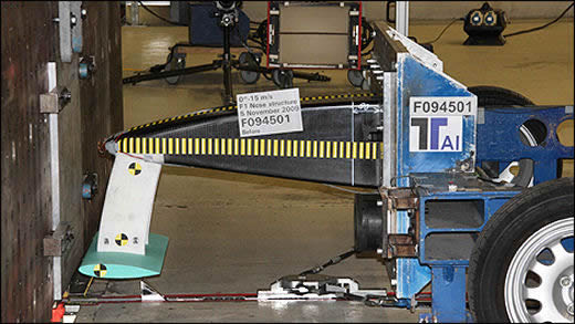
During the frontal impact test, fuel tank must be fitted and must be full of water. A dummy weighing minimum 75kg must be fitted with safety belt. Fire extinguisher must be fitted too. During the test, survival cell must be fitted on trolley, and all structure must weight 780 kg, and velocity of impact of no les then 15 m/sec.
The resistance of the test structure must be such that during the impact:
- The peak deceleration over the first 150mm of deformation does not exceed 10g;
- The peak deceleration over the first 60kJ energy absorption does not exceed 20g;
- The average deceleration of the trolley does not exceed 40g;
- The peak deceleration in the chest of the dummy does not exceed 60g for more than a cumulative 3ms, this being the resultant of data from three axes.
Furthermore, there must be no damage to the survival cell or to the mountings of the safety belts or fire extinguishers.
 |
 |
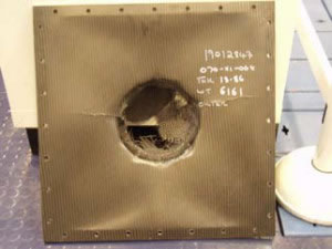
Fia crash test - pass |
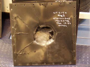
FIA crach test failure |
During side impact all parts which could materially affect the outcome of the test must be fitted to the test structure which must be solidly fixed to the ground and a solid object, having a mass of 780kg (+1%/-0) and traveling at a velocity of not less than 10 meters/second, will be projected into it. Object used to make impact must be positioned in order that its centre of area strikes the structure of the cockpit in predefined area. The resistance of the test structure must be such that during the impact:
- The average deceleration of the object, measured in the direction of impact, does not exceed 20g;
- The force applied to any one of the four impactor segments does not exceed 80kN for more than a cumulative 3ms;
- The energy absorbed by each of the four impactor segments must be between 15% and 35% of the total energy absorption.
Furthermore, all structural damage must be contained within the impact absorbing structure.
 |
|
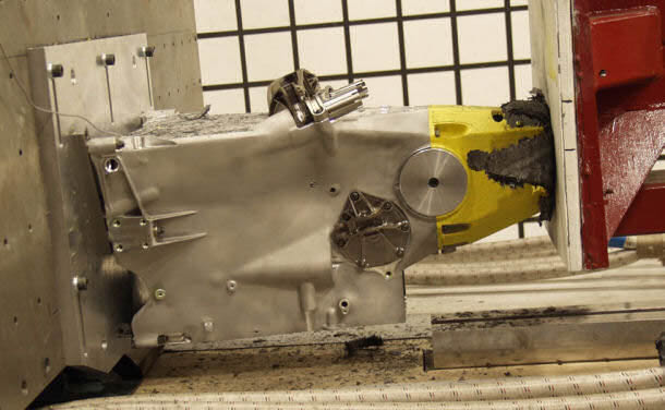
FIA rear impact test, impact structure is fitted on dummy gearbox |
|
 |
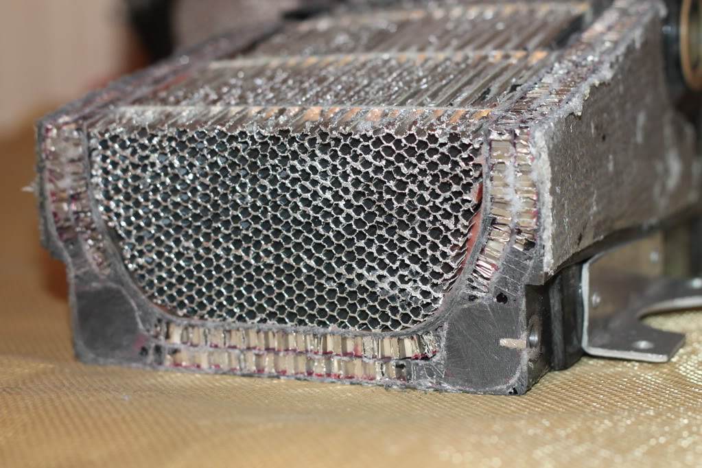 |
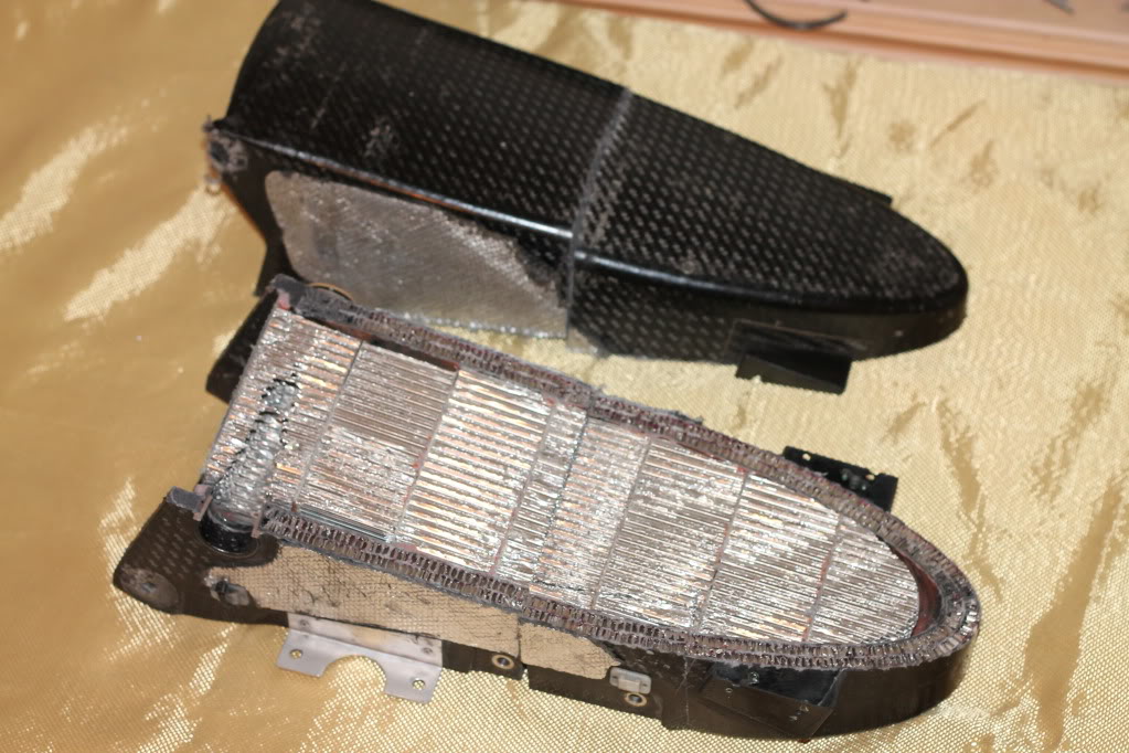
Cutout trough rear crash structure show complexity of the structure. Carbon fibre skin reinforced with aluminium honeycomb, and then wholl hollow structure is filled with elaborate arangement of aluminium honeycomb. This rear crash structure is from the late 1990's. |
|
During rear impact structure test, all parts which will be fitted behind the rear face of the engine and which could materially affect the outcome of the test must be fitted to the survival cell structure. If suspension members are to be mounted on the structure they must be fitted for the test. The structure and the gearbox must be solidly fixed to the ground and a solid object, having a mass of 780kg (+1%/-0) and traveling at a velocity of not less than 11 meters/second, will be projected into it. The resistance of the test structure must be such that during the impact:
- The peak deceleration over the first 225mm of deformation does not exceed 20g;
- The maximum deceleration does not exceed 20g for more than a cumulative 15ms, this being measured only in the direction of impact.
Furthermore, all structural damage must be contained within the area behind the rear wheel centre line.
Steering column, if hit with driver head must collapse. During steering column test, steering wheel, column and all parts that have an influence on the test must be fitted to a representative test structure. The test structure must be solidly fixed to the ground and a solid object, having a mass of 8kg (+1%/-0) and traveling at a velocity of not less than 7 meters/second will be projected into steering wheel. The object used for this test must be hemispherical with a diameter of 165mm (+/-1mm). For the test, the centre of the hemisphere must strike the structure at the centre of the steering wheel along the same axis as the main part of the steering column. The resistance of the test structure must be such that during the impact the peak deceleration of the object does not exceed 80g for more than a cumulative 3ms, this being measured only in the direction of impact. After the test, all substantial deformation must be within the steering column and the steering wheel quick release mechanism must still function normally.
Survival cell must have two roll protection structures. One, main roll structure is incorporated into engine air intake, and second is in front of the cockpit opening. During main roll structure test, a load equivalent to 50kN laterally, 60kN longitudinally in a rearward direction and 90kN vertically, must be applied to the top of the structure through a rigid flat pad which is 200mm in diameter and perpendicular to the loading axis. During the test, the roll structure must be attached to the survival cell which is supported on its underside on a flat plate, fixed to it through its engine mounting points.
During second roll structure test, a vertical load of 75kN must be applied to the top of the structure through a rigid flat pad which is 100mm in diameter and perpendicular to the loading axis. During the test, the rollover structure must be attached to the survival cell which is fixed to a flat horizontal plate.
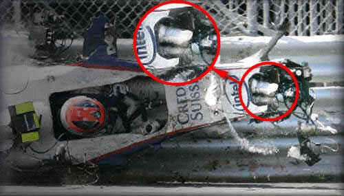
And with all this tests, safety must be improved even more. Ask Kubica's legs after Canadian GP 2006.
The chassis is constructed from certain panels – the so called “homologated panel” – that are regulated to achieve a required amount of penetration resistance in order to protect the driver. FIA 2012 season Technical and Sporting Regulations changes prescribe that to give better protection to the driver in the event that a car T-bones crash him from the side, the homologated intrusion panel is increased in height to 550mm above the reference plane (the same height as the highest part of the new nose regulation).
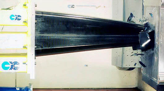
New revolutionary side impact system that works effectively regardless of the angle of impact will be implemented from season 2014. The teams agreed to implement this system for 2014 at the F1 Technical Working Group meeting on 17 May 2013. It is the result of a year-long collaboration between the FIA Institute and F1 teams to develop a side impact system that works effectively in every situation. The old side impact system deploys crushable tube structures attached to the side of the chassis. Although extremely effective during normal impacts, they can break off during oblique impacts due to the extremely high tangential forces that are generated during the first few milliseconds of an impact. Initial testing benchmarked performance of current structures using a new dynamic oblique impact test configuration. The testing concluded that the carbon tubes had far more potential to provide an efficient, lightweight and robust solution, able to manage impact loads effectively in both lateral and for-aft directions. The winning solution was based on an initial design by Marussia, before undergoing extremely detailed optimisation by Red Bull Racing – an evolution of the current system, but using high-performance carbon fibre with a very bespoke external and internal geometry and precise layup configuration. The tube has a common specification but how teams put it into their cars is entirely their business. The static tests that will be undertaken on the monocoque will determine the strength of the mounts and make sure that they are sufficient to support the tube. After that, it's down to the teams as to how they integrate it and how they design their car around it.
ARTICLE 15 : CAR CONSTRUCTION
15.2.2 The principal structure must pass a static load test details of which may be found in Article 17.2. Furthermore, each team must supply detailed calculations which clearly show that it is capable of withstanding the same load when the longitudinal component is applied in a forward direction.
15.5.4 The survival cell must also be subjected to six separate static load tests :
1) On a vertical plane passing through the centre of the fuel tank.
2) On a vertical plane passing through the rearmost point at which the outer end of the forward‐most front wheel tether would make contact with the survival cell when swung about the inner attachment.
3) On a vertical plane 375mm forward of the rear edge of the cockpit entry template.
4) From beneath the fuel tank.
5) On each side of the cockpit opening.
6) From beneath the cockpit floor.
Details of the test procedures may be found in Article 18.2.
15.5.5 To test the attachments of the frontal, side and rear impact absorbing structures static side load tests must be carried out. Details of these test procedures may be found in Articles 18.6, 18.8 and 18.9.2.
ARTICLE 16 : IMPACT TESTING
16.1 Conditions applicable to all impact tests :
16.1.1 All tests must be carried out in accordance with FIA Test Procedure 01/00, in the presence of an FIA technical delegate and by using measuring equipment which has been calibrated to the satisfaction of the FIA technical delegate. A copy of the test procedure may be found in the Appendix to these regulations.
16.1.2 Any significant modification introduced into any of the structures tested shall require that part to pass a further test.
16.1.3 The reference survival cell must have passed every static load test described in Articles 15.2,15.5.4 and 15.5.5 before being subjected to any impact test.
16.2 Frontal test 1:
All parts which could materially affect the outcome of the test must be fitted to the test structure which must be solidly fixed to the trolley through its engine mounting points but not in such a way as to increase its impact resistance. The fuel tank must be fitted and may contain water. A dummy weighing at least 75kg must be fitted with safety belts described in Article 14.4 fastened. However, with the safety belts unfastened, the dummy must be able to move forwards freely in the cockpit. The extinguishers, as described in Article 14.1 must also be fitted. For the purposes of this test, the total weight of the trolley and test structure shall be 780kg (+1%/‐0) and the velocity of impact not less than 15 metres/second.
The resistance of the test structure must be such that during the impact either :
a) The peak deceleration over the first 150mm of deformation does not exceed 10g.
b) The peak deceleration over the first 60kJ energy absorption does not exceed 20g.
c) The average deceleration of the trolley does not exceed 40g.
d) The peak deceleration in the chest of the dummy does not exceed 60g for more than a cumulative 3ms, this being the resultant of data from three axes.
Or :
a) The peak force over the first 150mm of deformation does not exceed 75kN.
b) The peak force over the first 60kJ energy absorption does not exceed 150kN.
c) The average deceleration of the trolley does not exceed 40g.
d) The peak deceleration in the chest of the dummy does not exceed 60g for more than a cumulative 3ms, this being the resultant of data from three axes.
Furthermore, there must be no damage to the survival cell or to the mountings of the safety belts or fire extinguishers.
This test must be carried out on the survival cell subjected to the higher loads in the tests described in Articles 18.2‐5, and on the frontal impact absorbing structure which was subjected to the test described in Article 18.6.
16.3 Frontal test 2 :
A 50mm (+/‐1mm) thick aluminium plate should be attached to the front bulkhead of the survival cell through the mounting points of the frontal impact absorbing structure. The plate should :
‐ Measure 375mm (+/‐1mm) wide x 375mm (+/‐1mm) high.
‐ Be fitted symmetrically about the car centre line.
‐ Be fitted in a vertical sense in order to ensure force distribution is similar to that
measured during the first frontal test.
‐ Have four M10 x 30mm holes in the outer face arranged in a 125mm square pattern about it's geometric centre. The test laboratory will then fit a 5mm thick 300mm x 275mm steel plate to these holes using a 5mm washer stack. All parts which could materially affect the outcome of the test must be fitted to the test
structure which must be solidly fixed to the trolley through its engine mounting points but not in such a way as to increase its impact resistance. The fuel tank must be fitted and must be full of water. A dummy weighing at least 75kg must be fitted with safety belts described in Article 14.4 fastened. However, with the safety belts unfastened, the dummy must be able to move forwards freely in the cockpit. For the purposes of this test, the total weight of the trolley and test structure shall be 900kg (+1%/‐0) and the velocity of impact not less than 15 metres/second.
The impact wall must be fitted with six 60kN crush tubes which develop a combined 360kN as follows :
‐ 2 x 60kN from T‐zero to T‐end, directed into the two lower M10 attachment points.
‐ 2 x 60kN from T‐100mm to T‐end, directed into the two upper M10 attachment points.
‐ 2 x 60kN from T‐200mm to T‐end, directed into the sled.
The resistance of the test structure must be such that following the impact there is no damage to the survival cell or to the mountings of the safety belts. This test must be carried out on the survival cell subjected to the higher loads in the tests
described in Articles 18.2‐5. Specifications of the crush tubes and test arrangement may be found in the Appendix to these regulations.
16.4 Side test :
All parts which could materially affect the outcome of the test must be fitted to the test structure which must be solidly fixed to the ground and a solid object, having a mass of 780kg (+1%/‐0) and travelling at a velocity of not less than 10 metres/second, will be projected into it.
The object used for this test must :
‐ Incorporate an impactor assembly, the specification of which may be found in the
Appendix to these regulations.
‐ Be positioned in order that its centre of area strikes the structure 300mm (+/‐25mm) above the reference plane and at a point 500mm (+/‐3mm) forward of the rear edge of the cockpit opening template. During the test the striking object may not pivot in any axis and the survival cell may be supported in any way provided this does not increase the impact resistance of the parts being tested. The impact axis must be perpendicular to the car centre line and parallel to the ground.
The resistance of the test structure must be such that during the impact :
‐ The average deceleration of the object, measured in the direction of impact, does not exceed 20g.
‐ The force applied to any one of the four impactor segments does not exceed 80kN for more than a cumulative 3ms.
‐ The energy absorbed by each of the four impactor segments must be between 15% and 35% of the total energy absorption.
Furthermore, all structural damage must be contained within the impact absorbing structure. This test must be carried out on the survival cell subjected to the higher loads in the tests described in Articles 18.2‐5 and on the side impact absorbing structure(s) which were subjected to the test described in Article 18.9.
16.5 Rear test :
All parts which will be fitted behind the rear face of the engine and which could materially affect the outcome of the test must be fitted to the test structure. If suspension members are to be mounted on the structure they must be fitted for the test. The structure and the gearbox must be solidly fixed to the ground and a solid object, having a mass of 780kg (+1%/‐0) and travelling at a velocity of not less than 11 metres/second, will be projected into it. The object used for this test must be flat, measure 450mm (+/‐3mm) wide by 550mm (+/‐3mm) high and may have a 10mm radius on all edges. Its lower edge must be at the same level as the car reference plane (+/‐3mm) and must be so arranged to strike the structure vertically and at 90 to the car centre line. During the test, the striking object may not pivot in any axis and the crash structure may be supported in any way provided this does not increase the impact resistance of the parts being tested.
The resistance of the test structure must be such that during the impact :
‐ The peak deceleration over the first 225mm of deformation does not exceed 20g.
‐ The maximum deceleration does not exceed 20g for more than a cumulative 15ms, this being measured only in the direction of impact.
Furthermore, all structural damage must be contained within the area behind the rear wheel centre line.
This test must be carried out on the rear impact absorbing structure which was subjected to the test described in Article 18.8.
16.6 Steering column test :
The parts referred to in Article 10.4.4 must be fitted to a representative test structure; any other parts which could materially affect the outcome of the test must also be fitted. The test structure must be solidly fixed to the ground and a solid object, having a mass of 8kg (+1%/‐0) and travelling at a velocity of not less than 7metres/second, will be projected into it. The object used for this test must be hemispherical with a diameter of 165mm (+/‐1mm). For the test, the centre of the hemisphere must strike the structure at the centre of the steering wheel along the same axis as the main part of the steering column. During the test the striking object may not pivot in any axis and the test structure may be supported in any way provided this does not increase the impact resistance of the parts being tested. The resistance of the test structure must be such that during the impact the peak deceleration of the object does not exceed 80g for more than a cumulative 3ms, this being measured only in the direction of impact. After the test, all substantial deformation must be within the steering column and the steering wheel quick release mechanism must still function normally.
ARTICLE 17 : ROLL STRUCTURE TESTING
17.1 Conditions applicable to both roll structure tests :
17.1.1 Rubber 3mm thick may be used between the load pads and the roll structure.
17.1.2 Both peak loads must be applied in less than three minutes and be maintained for 10 seconds.
17.1.3 Under the load, deformation must be less than 25mm in the case of the principal roll structure and 50mm in the case of the second roll structure, measured along the loading axis and any structural failure limited to 100mm below the top of the rollover structure when measured vertically.
17.1.4 Any significant modification introduced into any of the structures tested shall require that part to pass a further test.
17.2 Principal roll structure test :
A load equivalent to 50kN laterally, 60kN longitudinally in a rearward direction and 90kN vertically, must be applied to the top of the structure through a rigid flat pad which is 200mm in diameter and perpendicular to the loading axis.
During the test, the roll structure must be attached to the survival cell which is supported on its underside on a flat plate, fixed to it through its engine mounting points and wedged laterally by any of the static load test pads described in Article 18.2.
17.3 Second roll structure test :
A vertical load of 75kN must be applied to the top of the structure through a rigid flat pad which is 100mm in diameter and perpendicular to the loading axis.
During the test, the rollover structure must be attached to the survival cell which is fixed to a flat horizontal plate.
ARTICLE 18 : STATIC LOAD TESTING
18.1 Conditions applicable to all static load tests :
18.1.1 The tests described in Articles 18.2, 18.3, 18.4, 18.5, 18.6 and 18.9.2 must be carried out on the survival cell which will be subjected to the impact tests described in Article 16.
18.1.2 Every subsequent survival cell produced must also be subjected to the tests described in Articles 18.2, 18.3, 18.4 and 18.5.
However, the tests described in Articles 18.2.1, 18.3, 18.4 and 18.5 may be carried out on subsequent survival cells with peak loads reduced by 20%. During these tests (on deflections greater than 3.0mm), the deflection across the inner surfaces must not exceed 120% of the deflection obtained at 80% of the peak load during the first test.
18.1.3 Deflections and deformations will be measured at the centre of area of circular load pads and at the top of rectangular pads.
18.1.4 All peak loads must be applied in less than three minutes, through a ball jointed junction at the centre of area of the pad, and maintained for 30 seconds.
18.1.5 Following the tests described in 18.2, 18.3, 18.4 and 18.5, permanent deformation must be less than 1.0mm (0.5mm in 18.3 and 18.4) after the load has been released for 1 minute.
18.1.6 All tests must be carried out by using measuring equipment which has been calibrated to the satisfaction of the FIA technical delegate.
18.1.7 A radius of 3mm is permissible on the edges of all load pads and rubber 3mm thick may be placed between them and the test structure.
18.1.8 For the tests described in 18.2, 18.3, 18.4 and 18.5, the survival cells must always be produced in an identical condition in order that their weights may be compared. If the weight differs by more than 5% from the one subjected to the impact tests described in Articles 16.2 and 16.3 further frontal and side impact tests and roll structure tests must be carried out.
18.1.9 Any significant modification introduced into any of the structures tested shall require that part to pass a further test.
18.2 Survival cell side tests :
18.2.1 For test 1, referred to in Article 15.5.4, pads 100mm long and 300mm high, which conform to the shape of the survival cell, must be placed against the outermost sides of the survival cell with the lower edge of the pad at the lowest part of the survival cell at that section. A constant transverse horizontal load of 25.0kN will be applied and, under the load, there must be no structural failure of the inner or outer surfaces of the survival cell.
18.2.2 For test 2), referred to in Article 15.5.4, pads 200mm in diameter which conform to the shape of the survival cell, must be placed against the outermost sides of the survival cell. The centre of the pads must pass through the plane mentioned above and the mid point of the height of the structure at that section.
A constant transverse horizontal load of 30.0kN will be applied to the pads and, under the load, there must be no structural failure of the inner or outer surfaces of the survival cell and the total deflection must not exceed 15mm.
18.2.3 For test 3), referred to in Article 15.5.4, pads 200mm in diameter which conform to the shape of the survival cell, must be placed against the outermost sides of the survival cell. The centre of the pads must be located 350mm above the reference plane and on the vertical plane mentioned in Article 15.5.4.
A constant transverse horizontal load of 30.0kN will be applied to the pads and, under the load, there must be no structural failure of the inner or outer surfaces of the survival cell and the total deflection must not exceed 15mm.
18.3 Fuel tank floor test :
A pad of 200mm diameter must be placed in the centre of area of the fuel tank floor and a vertical upwards load of 12.5kN applied. Under the load, there must be no structural failure of the inner or outer surfaces of the survival cell.
18.4 Cockpit floor test :
A pad of 200mm diameter must be placed beneath the survival cell, on the car centre line and with its centre 600mm forward of the rear edge of the cockpit entry template, and a vertical upwards load of 15kN applied. Under the load, there must be no structural failure of the inner or outer surfaces of the survival cell.
18.5 Cockpit rim tests :
Two pads, each of which is 50mm in diameter, must be placed on both sides of the cockpit rim with their upper edges at the same height as the top of the cockpit side with their centres at a point 250mm forward of the rear edge of the cockpit opening template longitudinally. A constant transverse horizontal load of 15.0kN will then be applied at 90° to the car centre line and, under the load, there must be no structural failure of the inner or outer surfaces of the survival cell and the total deflection must not exceed 20mm.
This test must be repeated at positions 50mm and 150mm forward of the rear edge of the cockpit opening template longitudinally.
18.6 Nose push off test :
During the test the survival cell must be resting on a flat plate and secured to it solidly but not in a way that could increase the strength of the attachments being tested. A constant transversal horizontal load of 40.0kN must then be applied to one side of the impact absorbing structure, using a pad identical to the ones used in the lateral tests in Article 18.2.1, at a point 550mm from the front wheel axis.
The centre of area of the pad must pass through the plane mentioned above and the mid point of the height of the structure at the relevant section. After 30 seconds of application, there must be no failure of the structure or of any attachment between the structure and the survival cell.
18.7 Side intrusion test :
18.7.1 The test must be carried out in accordance with FIA Test Procedure 02/05, in the presence of an FIA technical delegate and by using measuring equipment which has been calibrated to the satisfaction of the FIA technical delegate. A copy of the test procedure may be found in the Appendix to these regulations.
18.7.2 The test panel must be 500mm x 500mm and will be tested by forcing a rigid truncated cone through the centre of the panel at a rate of 2mm (+/‐1mm) per second until the displacement exceeds 150mm.
During the first 100mm of displacement the load must exceed 250kN and the energy absorption must exceed 6000J. There must be no systematic damage to the border or damage to the fixture before these requirements have been met.
18.8 Rear impact structure push off test :
During the test the gearbox and the structure must be solidly fixed to the ground but not in a way that could increase the strength of the attachments being tested.
A constant transversal horizontal load of 40kN must then be applied to one side of the impact absorbing structure, using a pad identical to the ones used in the lateral tests in Article 18.2.1, at a point 400mm behind the rear wheel axis.
The centre of area of the pad must pass through the plane mentioned above and the mid point of the height of the structure at the relevant section. After 30 seconds of application, there must be no failure of the structure or of any attachment between the structure and the gearbox.
18.9 Side impact structure push off tests :
18.9.1 Each team must supply detailed calculations which clearly show that the structure(s) are capable of withstanding :
‐ Horizontal loads of 20kN applied separately in a forward and a rearward direction by a ball‐jointed pad, which may conform to the shape of the structure(s), measuring 550mm high x 100mm wide and whose centre of area lies 600mm from the car centre line and 300mm above the reference plane.
‐ A vertical load of 10kN applied in an upward or downward direction by a ball‐jointed pad, which may conform to the shape of the structure(s), measuring 400mm long x 100mm wide whose centre of area lies 600mm from the car centre line and 500mm forward of the rear edge of the cockpit entry template.
In all cases the calculations should show that there will be no structural failure of the parts. It should be assumed that ball‐jointed pads are used, the joint lying at the centre of area of the pad.
If multiple impact structures are fitted to the car only those in contact with the pads need have the load applied to them.
18.9.2 During the push off tests the survival cell must be resting on a flat plate and secured to it solidly but not in a way that could increase the strength of the attachments being tested. During the first test a constant rearward horizontal load of 20.0kN must then be applied to the impact absorbing structure(s) using a ball‐jointed pad 550mm high and 100mm wide, which may conform to the shape of the structure(s), whose centre of area lies 600mm from the car centre line.
The centre of area of the pad must lie 300mm above the reference plane and there must be no failure of any structure or of any attachment between the structure(s) and the survival cell. If multiple impact structures are fitted to the car only those in contact with the pads will be tested.
During the second test a constant upward vertical load of 10.0kN must then be applied to the impact absorbing structure(s) using a ball‐jointed pad 400mm long and 100mm wide, which may conform to the shape of the structure(s), whose centre of area lies 600mm from the car centre line.
The centre of area of the pad must lie 500mm forward of the rear edge of the cockpit entry template and there must be no failure of any structure or of any attachment between the structure(s) and the survival cell.
If multiple impact structures are fitted to the car only those in contact with the pads will be tested.